Redline Borosilicate Tube
Made from borosilicate glass, it is used in numerous applications where both chemical resistance and a low thermal expansion coefficient are required. The outer diameters of the level tube are available in various sizes, ranging from ½” to 1 ½”, and the lengths can vary up to 144″.
The level tube is available in different wall thicknesses according to the pressure requirements of the equipment, and it is supplied with diamond-cut ends and squared to ensure proper sealing and avoid sharp edges.
Red Line Tube – Features
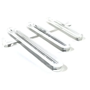
The red line tube is available in both red line and transparent versions. The red line version creates a special optical effect where the red line between the two white sides magnifies the central line, increasing the observation distance of the liquid. This type of tube is designed to enhance the visibility of fluid levels within a vessel. It uses red and white lines along its length to provide refracted amplification and a sharp contrast against the color of the fluid or background, making it easier to identify fluid levels at a glance. This red line feature offers a practical and efficient method for improving usability in industrial fluid management.
| Glass Type | Borosilicate 3.3 | |
|---|---|---|
| Manufacturing Parameters | ||
| Manufacturing Diameters | 1/2”, 5/8”, 3/4”, 7/8”, 1”, 1-1/4”, 1-1/2” | |
| Manufacturing Thicknesses | Standard wall, high pressure, and extra reinforced | |
| Minimum Manufacturing Length | 10 mm | |
| Maximum Manufacturing Length | 3700 mm | |
| Operating Parameters | ||
| Maximum Constant Operating Temperature | 500 °C | |
| Maximum Short-Term Operating Temperature | 560 °C | |
| Thermal Shock Resistance | 230 K | |
| Maximum Operating Pressure | *** (DIN7080) | |
| Chemical Properties | ||
| Hydrolytic Resistance | HGB 1 (ISO 719) | |
| Acid Resistance | Class S1 (ISO 1776) | |
| Alkaline Resistance | Class A2 (ISO 695) | |
| Chemical Composition | ||
| SiO2 | Min 80% Content | |
| B2O3 | Min 13% Content | |
| Na2O + K2O | Min 96% Content | |
Redline Borosilicate Tube – Recommendations
What to Do
- Inspect the level indicator glass daily, maintain maintenance records, and perform routine replacements.
- Install protective covers where necessary to protect personnel.
- Ensure that the level indicator glass, gland fittings, nuts, seals, etc., are the correct size and type before installation.
- Examine the level indicator glass for damage and ensure that the seals are free from hard deposits or tears.
- Remove all deposits from sealing areas, gland nuts, gland fittings (where used), and use new seals before installing the level indicator glass.
- Protect the exterior of the level indicator glass from sudden temperature changes, such as drafts, water spray, etc.
- Ensure the system is protected by a safety shutdown system (such as a safety ball or check valve).
What Not to Do
- DO NOT allow contact between the glass and metal.
- DO NOT subject the level indicator glass to bending or twisting forces.
- DO NOT allow the level indicator glass to come into contact with the bottom of the gland fitting.
- DO NOT strike, impact, or scratch the glass.
- DO NOT reuse any tubular glass, seals, or gaskets.
- DO NOT use glass that is scratched, chipped, or otherwise damaged. Used glass may contain damage and pose safety risks.
- DO NOT exceed the working pressures recommended by the glass or level indicator glass manufacturer, nor the maximum recommended length for tubular glass.
- DO NOT tighten the gland nut and gasket beyond the manufacturer’s recommended specifications for the level indicator glass.
- DO NOT operate the level indicator glasses unless the valve sets are equipped with drainage, ventilation, and a safety ball.
- DO NOT attempt to clean the glass while the unit is in operation. Cleaning should be done without removing the level indicator glass.
- DO NOT attempt to inspect the glass, adjust the clamping rods, nuts, or gland fittings, or inspect or tighten other fittings without isolating the level indicator glass from the pressure vessel and opening the drainage ventilation.
- DO NOT perform welding, impact, or sandblasting near the level indicator glass area without protecting the glass.
We are at your disposal to assist you. If you would like more information about our products or have any inquiries, we invite you to visit our contact page. Our team will be happy to assist you and provide you with all the information you need.